AstroEQ Tutorials Wiki
Adding an ST4 Port
While I recommend using PHD Guiding/EQMOD for guiding your mount, it is possible to add ST4 capabilities to the mount which will work even if EQMOD is connected, but *should* also work without a computer attached.
Adding an ST4 port is relatively simple, it is a case of soldering on 5 wires: RA+, RA-, DEC+, DEC- and GND. Instructions can be found below.
Arduino Mega:
For DIY controllers build with the Arduino Mega, the connections are as follows:
| Function | Arduino Pin |
|---|---|
| RA+ | Digital Pin 50 |
| RA- | Digital Pin 53 |
| DEC+ | Digital Pin 51 |
| DEC- | Digital Pin 52 |
The pins have internal pull-up resistors, so you can simply connect wires to these pins, and to the ground pin, and then solder on to an RJ11 6P6C type socket to attach your ST4 Cable.
If you don't want to solder on a connector, you can use the GPKIT-EQ which can be bought from Shoestring Astronomy. Essentially this is just the end from an RJ11 cable soldered onto the board, and then an RJ11 female to female coupler.
DIY ATMega162, or AstroEQ 4.0
For DIY controllers build around the preferred ATMega162 controller, the connections are as follows:
| Function | ATMega162 Pin |
|---|---|
| RA+ | Pin 32 [PA7] |
| RA- | Pin 35 [PA4] |
| DEC+ | Pin 33 [PA6] |
| DEC- | Pin 34 [PA5] |
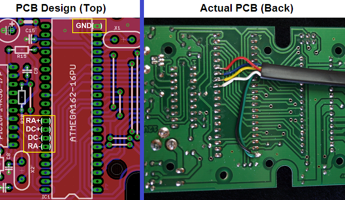
These assignments also apply to AstroEQ Controllers with Hardware Version 4.0. The version number is marked on the printed circuit board, but can also be identified by the fact that their isn't an ST4 socket footprint marked on the board. Later versions of AstroEQ were shipped with an unpopulated ST4 footprint.
For these, solder wires directly to the back of the PCB as pictured below:

If you don't want to solder on a connector, you can use the GPKIT-EQ which can be bought from Shoestring Astronomy. Essentially this is just the end from an RJ11 cable soldered onto the board, and then an RJ11 female to female coupler.
AstroEQ 4.1 or Newer
For all AstroEQ versions from 4.1 onwards, there is a footprint on the printed circuit board on which an ST4 connector can be directly soldered. The footprint is designed for the following low profile RJ11 connector which I know will fit inside the AstroEQ enclosure:
| Farnell Code | Description |
|---|---|
| 1536490 | MOLEX - 95501-2661 - MODULAR, JACK, THT, R/A, RJ11, 6P6C |
If you are looking for alternatives, you can use the datasheet from the farnell website to get dimensions, specifically the height of the connector.
You also need to connect the two four pin headers, JP1 and JP2. These are located one below the IC, and the other next to the ST4 footprint. They should be connected as Pin1 to Pin1, Pin2 to Pin2, etc. (Pin1 is marked by a square box). If you find that the pins perform the wrong action - e.g. DEC+ causes RA-, then you can change these four cables around to find the correct order.
The wires are connect to the RJ11 connector in the following manner:
| RJ11 Connector Pin | JP1/JP2 Pin Number | Meaning |
|---|---|---|
| 1 | N/C | N/C |
| 2 | N/C | GND |
| 3 | 4 | RA- |
| 4 | 3 | DEC- |
| 5 | 2 | DEC+ |
| 6 | 1 | RA+ |

